- ZK
- Guangdong,China
- 3-7working days
- 6000pcs/month
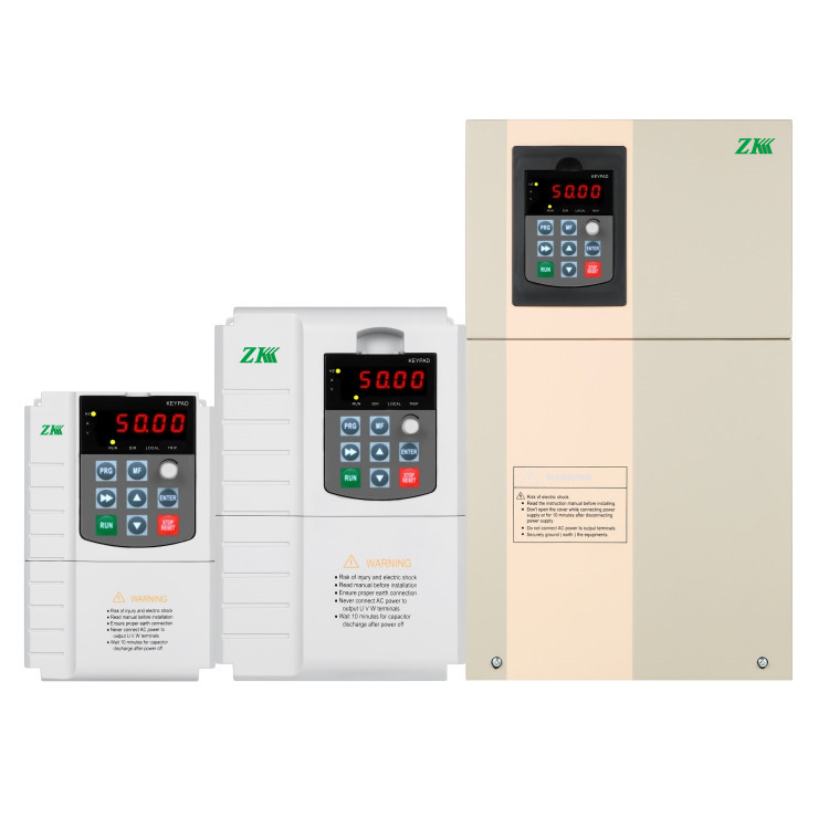
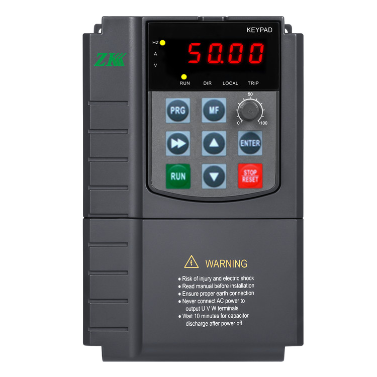
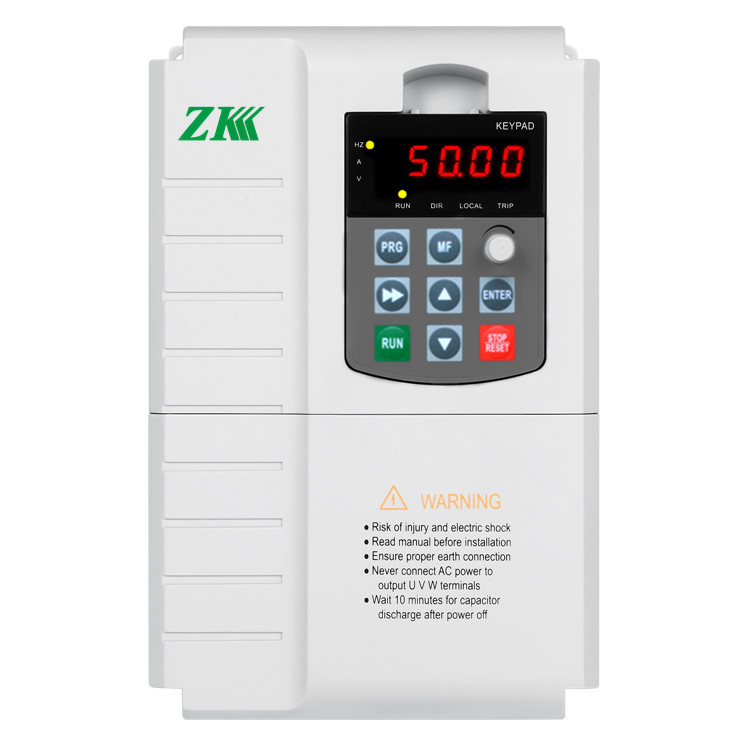
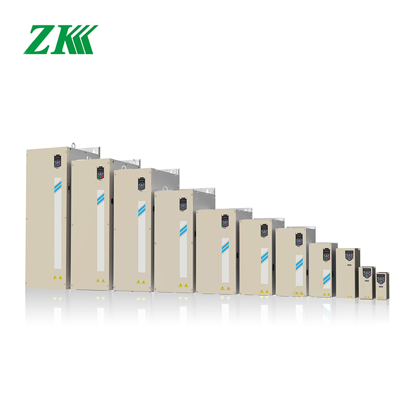
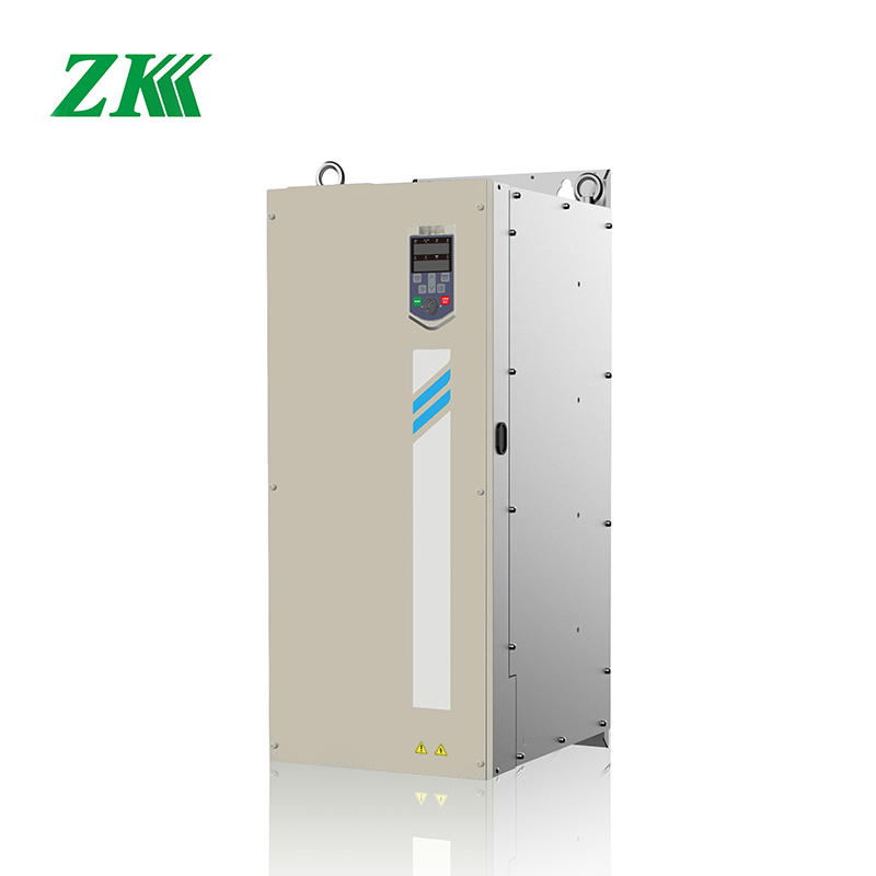
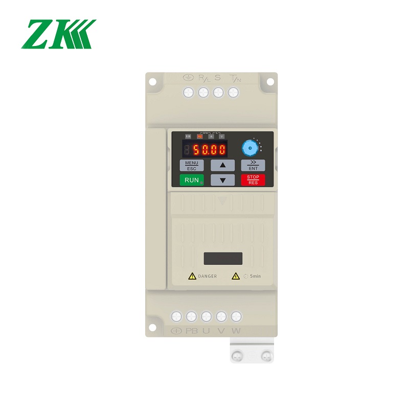
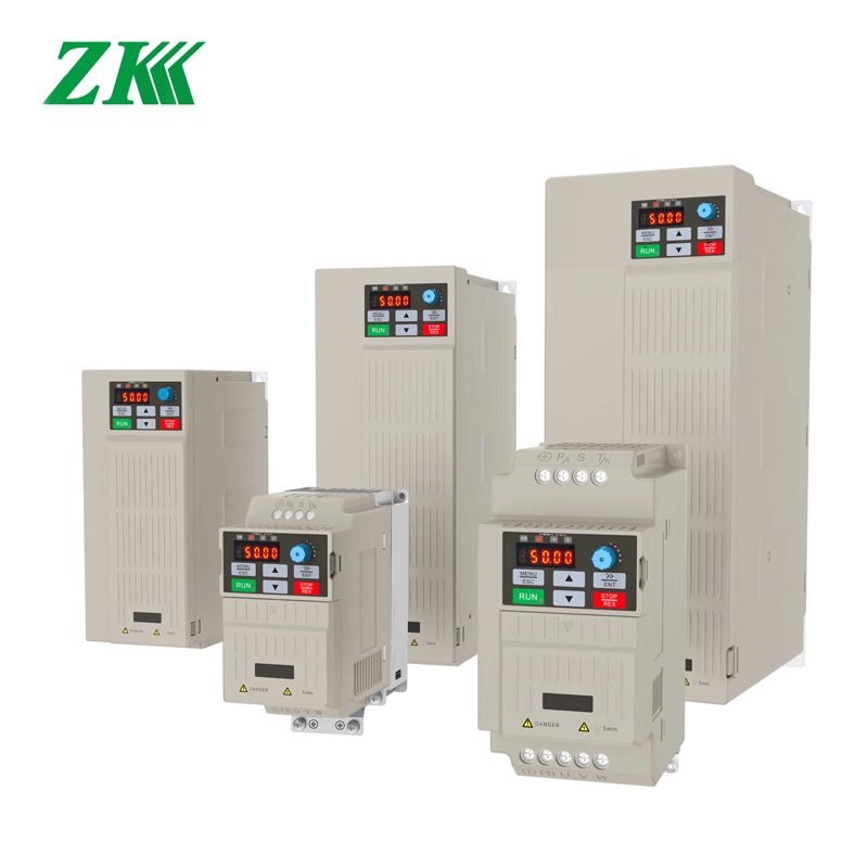
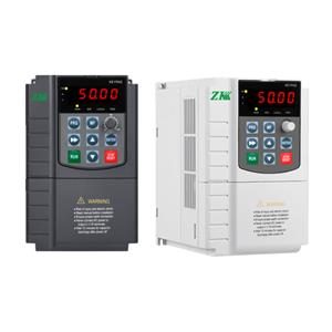
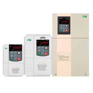
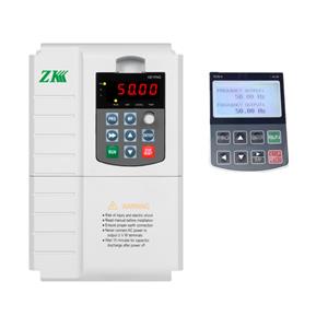
S100 series is a high performance General Purpose Frequency Inverter with current vector control. It mostly used to control and adjust the speed and torque of the 3 phase induction motor and also PMSM. It adopts mature platform of software and hardware with a high level standard design.
S100 adopts high performance VECTOR control technology, higher torque output in low speed. Good dynamic characteristics, super overload capacity to make it easy to meet the demands of variable applications.
S100 variable frequency drive introduction:
1. S100 is a high reliability and high software performance motor drive with rich and perfect software&hardware functions to meet the application needs of most industrial sites;
2. S100 can drive asynchronous motor and permanent magnet synchronous motor(PMSM) simultaneously. It could run with vector control without PG card, vector control with PG card, speed/torque control and position servo control.
3. Adopt advanced software vector control algorithm, which can provide high performance open loop vector control for asynchronous motor and synchronous motor. Meanwhile, simple vector control of asynchronous motor and synchronous motor can be used to meet the requirements of general speed adjustment application.
4. Built-in PID controller, the improved PID function can satisfy most of the on-site process control, such as the closed-loop control of temperature, pressure and flow.
5. Multiple protection function to ensure the safety of the drive and motor.
6. Standard 485 communication interface, support Modbus/RTU communication protocol, direct and upper computer communication for field bus control; Profibus-DP and CAN function also optional.
Variable frequency inverter the designation rules of S100 series:
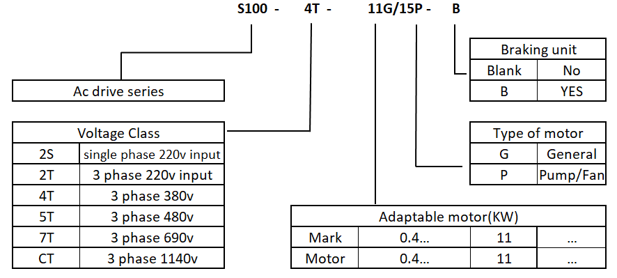
Models and specification:
Single phase 220v±15%, 50/60Hz
Model | KVA | Input current(A) | Output current(A) | Adaptable motor(KW) |
S100-2S-0.4GB | 1 | 3.4 | 2.1 | 0.4 |
S100-2S-0.7GB | 1.5 | 5 | 3.8 | 0.75 |
S100-2S-1.5GB | 3 | 5.8 | 5.1 | 1.5 |
S100-2S-2.2GB | 4 | 10.5 | 9 | 2.2 |
S100-2S-4.0GB | 5.9 | 14.6 | 13 | 4 |
Three-phase 380v±20%, 50/60Hz
Model | Power capacity (KVA) | Input current(A) | Output current(A) | Adaptable motor(KW) |
S100-4T-0.7GB | 1.5 | 3.4 | 2.1 | 0.75 |
S100-4T-1.5GB | 3 | 5 | 3.8 | 1.5 |
S100-4T-2.2GB | 4 | 5.8 | 5.1 | 2.2 |
S100-4T-4.0G/5.5PB | 5.9 | 10.5 | 9 | 3.7 |
S100-4T-5.5G/7.5PB | 8.9 | 14.6 | 13 | 5.5 |
S100T-4T-7.5G/11PB | 11 | 20.5 | 17 | 7.5 |
S100-4T-11G/15PB | 17 | 26 | 25 | 11 |
S100-4T-15G/18.5PB | 21 | 35 | 32 | 15 |
S100-4T-18.5G/22PB | 24 | 38.5 | 37 | 18.5 |
S100-4T-22G/30PB | 30 | 46.5 | 45 | 22 |
S100-4T-30G/37P | 40 | 62 | 60 | 30 |
S100-4T-37G/45P | 57 | 76 | 75 | 37 |
S100-4T-45G/55P | 69 | 92 | 91 | 45 |
S100-4T-55G/75P | 85 | 113 | 112 | 55 |
S100-4T-75G/90P | 110 | 153 | 150 | 75 |
S100-4T-90G/110P | 130 | 182 | 180 | 90 |
S100-4T-110G/132P | 160 | 214 | 210 | 110 |
S100-4T-132G/160P | 192 | 232 | 253 | 132 |
S100-4T-160G/185P | 200 | 290 | 304 | 160 |
S100-4T-185G/200P | 220 | 330 | 340 | 185 |
S100-4T-200G/220P | 250 | 360 | 380 | 200 |
S100-4T-220G/250P | 280 | 385 | 426 | 220 |
S100-4T-250G/280P | 355 | 437 | 470 | 250 |
S100-4T-280G/315P | 396 | 498 | 530 | 280 |
S100-4T-315G/355P | 455 | 586 | 600 | 315 |
S100-4T-355G/400P | 500 | 624 | 660 | 355 |
S100-4T-400G/450P | 560 | 680 | 690 | 400 |
S100-4T-450G/500P | 630 | 755 | 770 | 450 |
S100-4T-500G/560P | 700 | 840 | 860 | 500 |
Technical specification:
| Items | Specification | |||
| Control mode | Control mode | V/F control | Sensorless in open loop | Close loop vector control |
| Starting torque | 0.5Hz 150% | 0.5Hz 180% | 0.00Hz 180% | |
| Speed adjust range | 0:50 | |||
| Speed stabilizing precision | ±1% | ±0.1% | ±0.02% | |
| Torque precision | NO | NO | ±5% | |
| Motor type | General induction motor permanent magnet synchronous motor (PMSM ) | |||
| Function design | Highest frequency | General vector control :320Hz V/f control: 3200Hz | ||
| frequency resolution | Digital setting: 0.01Hz Analog setting:maximum×0.025% | |||
| Carrier frequency | 0.5K ~ 16KHz, the carrier frequency can be adjusted by temperature automatically | |||
| Frequency reference setting method | Digital of Control panel, analog AI1, AI2, potentiometer of control panel,UP/DN control, communication, PLC pulse frequency | |||
| Acceleration./dec eleration characteristic | Linear curve and S curve accel. /decel. mode, range of time: 0.0 to 65000S. | |||
| V/F curve | 3 mode: linear, multiple points, N Power | |||
| V/F separation | 2 times separation: totally separation, half separation | |||
| DC braking | DC braking frequency: 0.0 to 300Hz, DC braking current: 0.0% to 100% | |||
| Braking unit | Standard built in for up to 4T22G (22kw), optional built it for 4T30G~ 4T110G (30kw to 110kw), external built for above 4T160kw . | |||
| Jog function | Job frequency range: 0.0 to 50.0Hz, the acceleration and deceleration time of Jog | |||
| Configured PID function | Easy to perform pressure, flow, temperature close loop control | |||
| PLC multiple speed | To achieve 16 segment speed running through built in PLC or terminal control | |||
| Common Dc bus | Multiple drives use one DC bus for energy balance. | |||
| Auto voltage regulation (AVR) | Enable to keep output voltage constant when grid fluctuation | |||
| Over load tolerance capability | G type model: 150% rated current for 60s, 180% rated current for 3s, P type Model: 120% rated current for 60s, 150% rated current for 3s. | |||
| Stall protection control when over current, over voltage | Carry out limiting automation for running current, voltage to prevent over current, over voltage frequently | |||
| Rapid current limit function | Minimize the IGBT module broken to protect the AC Drive, maximum reduce the over current faul | |||
| Torque limit and torque control | "Excavator" characteristics , torque limit automatically during motor running. Torque control is available in close loop vector control mode. | |||
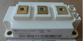
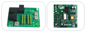
| 1. IGBT module using: Using the latest generation of INFINEON/FUJI brand which is the best choose for inverter application. | 2. Stronger protection: All-around test the components and temperature rise. Output ground short circuit protection,relay (contactor) actuation fault protection,brake circuit over current, brake tube over load etc protection to improve the system security. |
 |  |
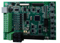
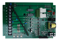
| 3. Conformal coating with reliability and stabilization: Professional design with three proofing coating process,good EMC performance. | 4. Optimizing hardware design to reduce the fault: PCB board 4 layer design to reduce “fly” wire and improve stability. 3 current sensor enhance the output protection. |
 |  |
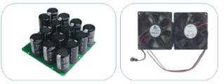
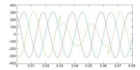
| 5. Longer life running:Quality components using to guarantee the inverter to have a longer life for work | 6. Wide voltage design: Full consideration of the grid voltage fluctuation and unbalance. |
 |  |

