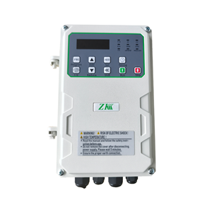
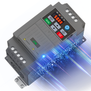
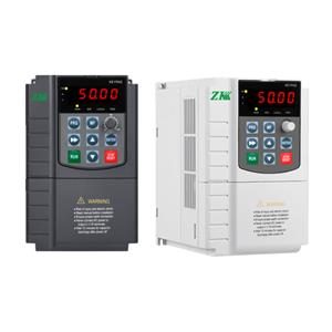
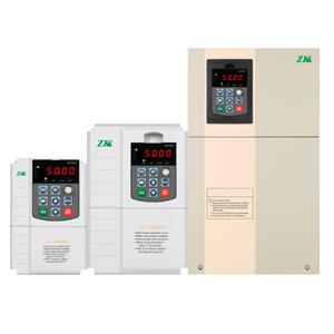
The easiest way to judge whether a frequency inverter is good or bad
The quality of the frequency converter cannot be seen. The easiest way to judge the quality of a frequency converter is to test it with power on; it is best to connect a motor whose power is less than the rated power of the frequency converter at the output end of the frequency converter during detection, so that you can know Its internal software is good or bad, especially after power-on, high torque at low frequency is a direct and effective method to test the inverter algorithm. After changing the parameters, adjust the inverter within 5HZ to see if the torque of the load motor is weakened, and the speed of the motor. Whether it changes uniformly, and then observe whether the output waveform of the inverter is perfect, and whether it starts and stops frequently in a short period of time to see the peak value of current and voltage, these methods can test the performance of the inverter software.
Before power-on, use the 1KΩ gear of a multimeter to check its input side R, S, T; the resistance values of U, V, W on the output side to determine whether the inverter can be powered on.
First disconnect the incoming lines R, S, T and outgoing lines ∪, V, W of the inverter, and then measure whether the rectifier circuit and the inverter circuit are normal.
1. Test the rectifier circuit part.
Adjust the multimeter to the resistance X1KΩ gear, the red test lead is connected to the P terminal, and the black test lead is connected to the R, S, and T terminals in turn. There should be a resistance value of about tens of kiloohms, and they are basically the same. Connect the black test lead to the P terminal, and the red test lead to R, S, and T in turn, with a resistance value close to infinity. Connect the red test lead to the N terminal, repeat the above steps, and you should have the same result. If the three-phase resistance is unbalanced or the resistance is infinite when the red test lead is connected to the P terminal, it can be determined that the circuit is abnormal and the rectifier bridge is faulty.
2. Check the inverter circuit.
Connect the red test lead to the P terminal and the black test lead to U, V and W in turn. There should be a resistance value of several tens of kiloohms, and the resistance value of each phase is basically the same. Connect the black test lead to the P terminal and the red test lead to U in turn. , V, W, have a resistance value close to infinity. Connect the black test lead to the N terminal, and repeat the above process to obtain the same result, otherwise it can be determined that the inverter module is faulty.
The power-on test can be performed only when the above detection is normal. Before and after power-on, determine the fault and its cause according to the fault display content. See if there are normal display results.
Be very careful during the whole power-on detection. Once there is smoke, or there is abnormal sound or odor, immediately cut off the input power supply, and see what the fault code is on the display panel of the inverter at this time.
If everything is normal, you can press the setting key on the panel at this time to perform panel operation or terminal control, frequency setting, acceleration and deceleration settings, etc.
For inverters of different manufacturers, you need to read the corresponding instruction manual.
Only in this way can it be preliminarily judged whether the inverter can be used.


